 Dear readers, Catholic Online was de-platformed by Shopify for our pro-life beliefs. They shut down our Catholic Online, Catholic Online School, Prayer Candles, and Catholic Online Learning Resources essential faith tools serving over 1.4 million students and millions of families worldwide. Our founders, now in their 70's, just gave their entire life savings to protect this mission. But fewer than 2% of readers donate. If everyone gave just $5, the cost of a coffee, we could rebuild stronger and keep Catholic education free for all. Stand with us in faith. Thank you. Help Now >
Evidence of 9+ foot thick Large Block of concrete at the bottom of Main Spillway? Large Void Chasms under Spillway? DSOD Inspectors told not to fix until damaged?
FREE Catholic Classes
Evidence of a 9+ foot thick Large Block of concrete at the bottom of the Main Spillway? Reveals dangerously large voids have formed in the past near the spillway"blowout" failure area? DSOD Inspectors told not to fix until damage occurs from "heavy flows"? Will this evidence of "Large Blocks" in "void fill" from possible under spillway slab erosion chasms derail DWR's narrative of any known failure indicators?
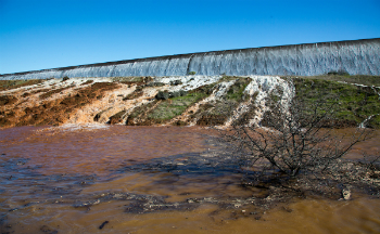
On February 11, 2017, water topped the Oroville spillway as the dam threatened to give way under the immense pressure of a full reservoir and eroding rainfall.
Highlights
Catholic Online (https://www.catholic.org)
5/31/2017 (8 years ago)
Published in Green
Keywords: Oroville, Dam, Spillway, Concrete, Catastrophic, Voids, Blocks, DSOD, DWR, Failure
LOS ANGELES, CA (California Network) - In January 12, 2000, a California Division of Safety of Dams (DSOD) Inspector had noted areas identified as "drummy patches" on the main spillway [1]. These "patches" were acoustic echo tones that indicated voids large enough, from the dB level of acoustic response, to where the Inspector felt these were important enough to note these findings in the report. Typical "sounding" methods, in the early dam spillway inspection era, involved dragging heavy chains or hammering the top concrete to create acoustic stimulation. Alarmingly, this DSOD report stated that "No treatment is proposed until they [drummy patches] are damaged by heavy flow." Why wait for the spillway to be "damaged" from a "heavy flow" condition? This report was 17 years ago. Was DWR operating in this "wait until failure" methodology instead of proactively investigating & fixing potential catastrophic failures? This DSOD inspection report seems to infer a "reactive" failure response atmosphere. Is this key to the demise of the spillway?
The Blowout failure area has likely revealed a key piece of evidence of DWR performing "deep" filling of dangerous chasms under the main spillway in over a number of years in "void filling" repairs. The "evidence" is a large block of concrete that originated just above the "blowout" failure area in the spillway. Does this block reveal evidence of actions of serious repair attempts to a large scale underslab "void erosion" cavity to which the scale of its size would have been threatening a major failure of the spillway for years?
This sequence of photographs and images possibly reveals that DWR has been "filling" dangerous chasms of large voids instead of recognizing the serious nature of the imminent failure of the Main Spillway. This evidence, if found to be as it shows, would be severely damaging to DWR's position of not being aware of any failure risk to the Main Spillway.
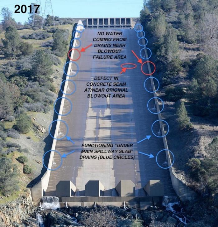
Fig 1. Red Circled side drains - missing drain flows near failure area. Large voiding likely would cause drain pipe to "fall" into the voids. Injection of void fill material could enter the exposed drain pipe ends and into the drain piping, causing a plugging. The void inducement of "dropped" pipe may also prevent water from collecting as the drains would have missing sections.
![Fig 2. Side view of the Large Block. Slab bottom seam visible. The bottom layer of the slab with a 'clean' seam reveals that the underside of the slab was 'washed'. No visible remains of material observed from the original construction compacted aggregate foundation before the pour of spillway slabs. A 'Clean seam' also notes that the large body of void area fill could not be from a 'pre-grade concrete fill' as the original construction compacted aggregate would have left a small 'void channel' between the slab and the lower block. No 'void channel' is present. The depth of the void fill is measured at a 7.7 foot thickness of 'concrete fill' if accounting for a 20 inch thickness of the top slab. Confirming dimensions are through vanishing line compensation & the construction height dimensions of the chute blocks (HYD-510 report [2]). Fig 2. Side view of the Large Block. Slab bottom seam visible. The bottom layer of the slab with a 'clean' seam reveals that the underside of the slab was 'washed'. No visible remains of material observed from the original construction compacted aggregate foundation before the pour of spillway slabs. A 'Clean seam' also notes that the large body of void area fill could not be from a 'pre-grade concrete fill' as the original construction compacted aggregate would have left a small 'void channel' between the slab and the lower block. No 'void channel' is present. The depth of the void fill is measured at a 7.7 foot thickness of 'concrete fill' if accounting for a 20 inch thickness of the top slab. Confirming dimensions are through vanishing line compensation & the construction height dimensions of the chute blocks (HYD-510 report [2]).](https://www.catholic.org/files/images/media/14962499251961_700.jpg)
Fig 2. Side view of the Large Block. Slab bottom seam visible. The bottom layer of the slab with a "clean" seam reveals that the underside of the slab was "washed". No visible remains of material observed from the original construction compacted aggregate foundation before the pour of spillway slabs. A "Clean seam" also notes that the large body of void area fill could not be from a "pre-grade concrete fill" as the original construction compacted aggregate would have left a small "void channel" between the slab and the lower block. No "void channel" is present. The depth of the void fill is measured at a 7.7 foot thickness of "concrete fill" if accounting for a 20 inch thickness of the top slab. Confirming dimensions are through vanishing line compensation & the construction height dimensions of the chute blocks (HYD-510 report [2]).
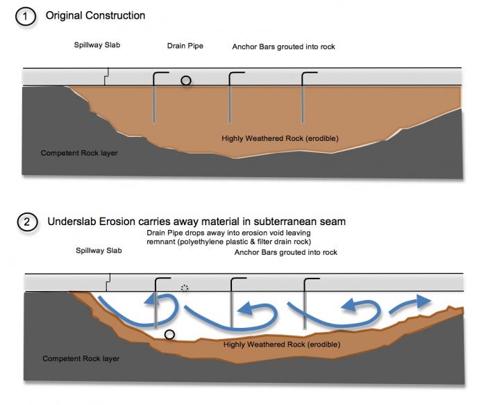
Fig 3. Evidence of the formation process of the Large Block "void fill". The original spillway was emplaced upon a channel of highly weathered rock. Anchor bars, with a 5 foot length extension below the spillway slab, were encased in grout from NX size drill holes into the substandard rock. The poor sealing design of the original spillway allowed volumes of pressurized waterflow to scour beneath the slabs from operation. Over time, this scouring eroded the highly weathered rock and created large voids under the slab. The slabs were thus acting like "bridges" over the voids. The risk to failure was great in these conditions as the anchorage from the anchor bars were greatly compromised, or even became completely isolated from rock by full "encasement" (See Fig 4).
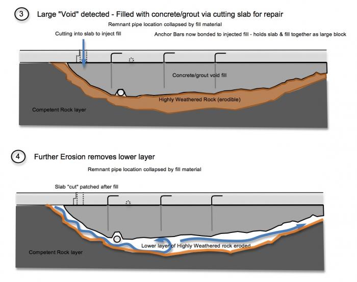
Fig 4. Evidence of the formation process of the Large Block "void fill" - continued. DSOD inspectors identified "drummy patches" in a method of striking the top surface of the spillway concrete and then listening for the acoustic echo response (See Fig 13). Some early methods to this technique is to use heavy chains to induce the vibratory acoustic stimulation. Other inspection methods use light tapping from hammers on the top surface. When a void area is detected, a process of repairing the void is to inject grout or a concrete material. However, this voiding was so significant in depth and volume that alarms should have been raised regarding the structural issue of the cause of the voiding (massive erosion in a large seam of highly frangible weathered rock). A fatal mistake occurs from the lack of recognition of this failure mode as DWR simply "fills in the massive void". The fatal mistake is that the anchor bars no longer have any structural (or greatly compromised) ability to secure the slab. The injected fill would entomb "all of" or nearly all of the ends of the protruding "anchor bars".
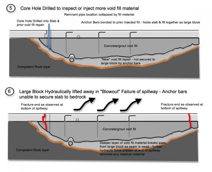
Fig 5. Evidence of the formation process of the Large Block "void fill" - continued. Further erosion under the first large void repair causes a new void that is deeper below the upper layer void fill concrete. Failure becomes inevitable as the slabs are at the mercy of "slumping", "hydraulic jacking", and "cavitation" failure modes. The Large Block was "lifted" up and moved down the spillway by powerful hydraulic forces during the blowout failure. Evidence suggests that this large "void fill" erosion problem could been in an area as wide as 80 feet and as long as 40 to 100 feet long (nearly 4 complete slab dimensions) (See Fig 8). The shear angle and force of breakage to the thickness of the Large Block indicates that a subsequent "shock collision" of this block caused the fracture (See Fig 7a).
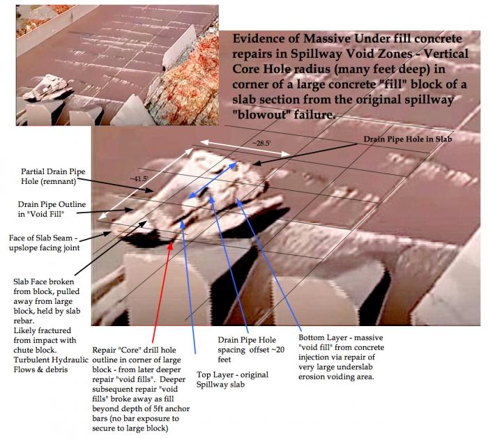
Fig 6. Dimensional evidence of the Large Block. Block rotated after either being fractured and "lifted" out of the spillway or by backcutting erosion & collapse by hydraulic forces. Note: Image color enhanced for sharpness and detail. The face of the end section of the block was likely broken from the main block when it impacted the chute block. Additional turbulent flows and debris strikes likely extended this broken end section away from the main block as observed by the exposed rebar & the mating outline seam match of the end section to the main block. In this image, the block length was first identified to be a close match to the width of a spillway slab (40 feet). This was later confirmed by additional photographic evidence (See Fig 7).
![Fig 7. Top View of Block. More accurate measurements from new imaging reveal the length of the block is very close to 40.0 feet when compensating for the 'extension' breakage of the top piece. Slab top layer rebar holds this piece to the large block body. The opposing ends of the slab have matching smooth features of the 'expansion seam' design as noted in HYD-510 construction specifications [2]. The 'Repair' Core hole location (red circle - See Figs 6, 11, 12) would be a close match to the corner of the 'extension' breakage. This would nominally place the Core hole at or near a corner junction seam in the 40 foot long block. The thickness of the top slab reveals a taper to the thinnest dimension of 17.28 inches towards the core hole end. This 'taper profile' of the slab thickness has been found to match the cross sectional views of the currently exposed upper main spillway section, where the thinnest section taper is in the middle or center line of the spillway. Thus, this infers that this slab block was located to the left or the right in the center of the spillway. The two possible orientations, given the 40 foot alignment to the spillway upslope, would be upslope left (1) or upslope right (2). The corresponding core holes would likely align with surface repair patching or 'concrete cuts into the slab' that would be observable on the pre-blowout failure spillway concrete (See Fig 7a). Fig 7. Top View of Block. More accurate measurements from new imaging reveal the length of the block is very close to 40.0 feet when compensating for the 'extension' breakage of the top piece. Slab top layer rebar holds this piece to the large block body. The opposing ends of the slab have matching smooth features of the 'expansion seam' design as noted in HYD-510 construction specifications [2]. The 'Repair' Core hole location (red circle - See Figs 6, 11, 12) would be a close match to the corner of the 'extension' breakage. This would nominally place the Core hole at or near a corner junction seam in the 40 foot long block. The thickness of the top slab reveals a taper to the thinnest dimension of 17.28 inches towards the core hole end. This 'taper profile' of the slab thickness has been found to match the cross sectional views of the currently exposed upper main spillway section, where the thinnest section taper is in the middle or center line of the spillway. Thus, this infers that this slab block was located to the left or the right in the center of the spillway. The two possible orientations, given the 40 foot alignment to the spillway upslope, would be upslope left (1) or upslope right (2). The corresponding core holes would likely align with surface repair patching or 'concrete cuts into the slab' that would be observable on the pre-blowout failure spillway concrete (See Fig 7a).](https://www.catholic.org/files/images/media/14962500621961_700.jpg)
Fig 7. Top View of Block. More accurate measurements from new imaging reveal the length of the block is very close to 40.0 feet when compensating for the "extension" breakage of the top piece. Slab top layer rebar holds this piece to the large block body. The opposing ends of the slab have matching smooth features of the "expansion seam" design as noted in HYD-510 construction specifications [2]. The "Repair" Core hole location (red circle - See Figs 6, 11, 12) would be a close match to the corner of the "extension" breakage. This would nominally place the Core hole at or near a corner junction seam in the 40 foot long block. The thickness of the top slab reveals a taper to the thinnest dimension of 17.28 inches towards the core hole end. This "taper profile" of the slab thickness has been found to match the cross sectional views of the currently exposed upper main spillway section, where the thinnest section taper is in the middle or center line of the spillway. Thus, this infers that this slab block was located to the left or the right in the center of the spillway. The two possible orientations, given the 40 foot alignment to the spillway upslope, would be upslope left (1) or upslope right (2). The corresponding core holes would likely align with surface repair patching or "concrete cuts into the slab" that would be observable on the pre-blowout failure spillway concrete (See Fig 7a).
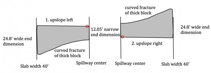
Fig 7a. Original orientation "fit" possibilities of slab block prior to pre-blowout failure. Due to the thickness of an average near 6.23 ft along the curved "fracture" breakage face, the block likely was broken from collision forces during "lifting" and then "drop & tumbling" on the lower main spillway when the flows were increased to 100,000 cfs after Feb 10, 2017.
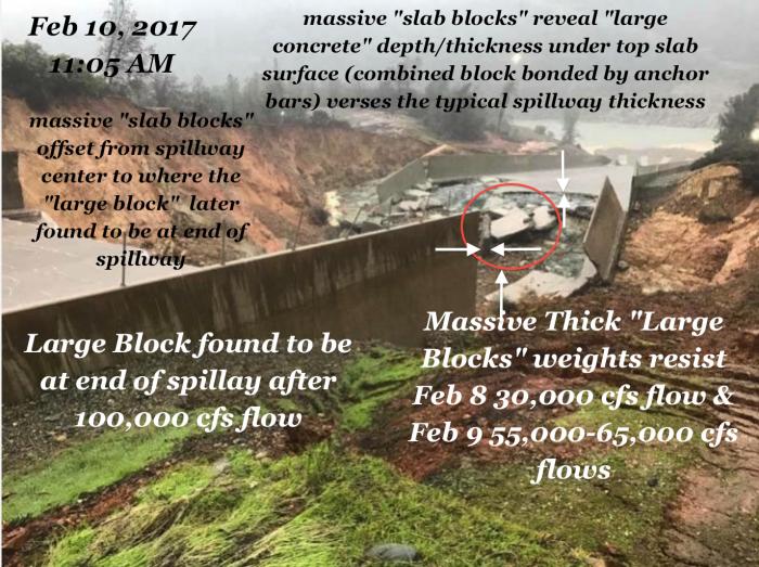
Fig 8. Massive thick "Large Blocks" stacked at blowout-failure area near top of broken main spillway. These blocks originated just above the original "blowout" failure hole in the spillway. The Slab Blocks reveal the evidence of the large "void filling" in the highly weathered rock section of the main spillway. The blocks were massive enough in weight to remain by withstanding flows of 30,000 cfs Feb 8, 2017 and 55,000 cfs and 65,000 cfs flows Feb 9, 2017. Only after the 100,000 cfs flow period were these blocks removed and also this is when the single Large Block was found at the bottom of the spillway lodged against the Spillway Chute Block. The thickness of these Large Blocks reveal the amplified danger of instability that was created by "void repair concrete" enveloping the anchor bars (See Figs 3, 4, 5). Deep erosion of the underslab substructure rock should have alerted DWR to this instability danger. DWR should have recognized the seriousness of the erodibility of the substructure rock from the presence of these massive voids. At a minimum - Proper repairs would have entailed a "rebuild" replacement of these under "voiding" affected spillway slabs and removal of the highly erodible substructure rock. This effort likely would have revealed the extent of the design flaws and weaknesses of the original spillway design. Thus, the likelihood of a modern retrofit and/or analysis of the entire spillway would have been realized if this original condition was properly addressed. Instead, DWR greatly amplified a spillway failure danger by simply filling in the huge voiding areas, thus removing the structural integrity of the anchor bars.
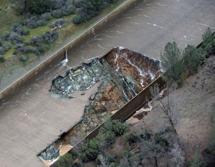
Fig 9. Original "Blow-out" failure of Main Spillway. No "Large Blocks" present. The upper failure seam in the spillway is where seepage has been observed originating in the spillway during non-operating conditions (dry - See Fig 14). This seam is also where multiple repairs have been performed over the years as evidenced in images of "cuts" in the slab concrete for nearly the full length of this seam. After additional flows of 30,000 cfs to 33,000 cfs on Feb 8, 2017, and then 45,000 cfs on Feb 9, 2017, is when rapid upslope spillway backcutting collapsing failure progressed. This "rapid upslope" spillway collapse was most likely accelerated by the unstable large "void fill" blocks that had little to no anchor bar integrity remaining. The spillway flow was stopped on Feb 10, 2017 for an inspection (See Fig 8.). That is when the stack of "large slab blocks" were observed washed to the far side of the erosion channel, abutting the still intact broken upper part of the lower spillway. This is the critical evidence that the "large slab blocks" originated just above this "original blow-out failure" location & in the same large highly erodible weathered rock seam (Fig 8.).
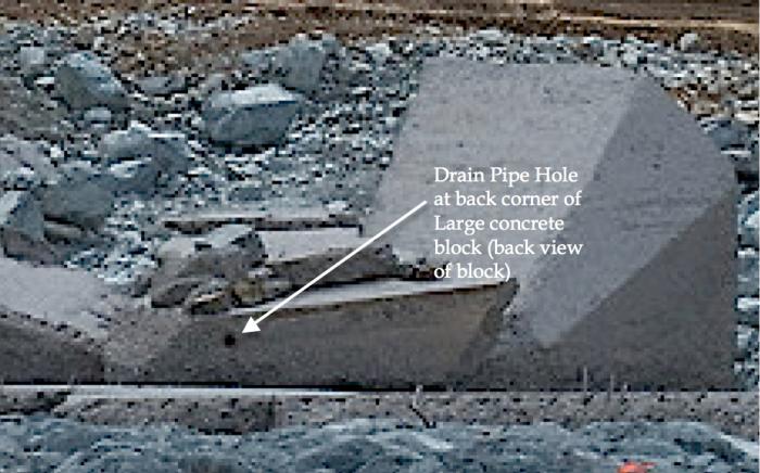
Fig 10. This Drain Pipe Hole is full size in contrast to the "remnant" pipe outline. See Figs 3, 4, for process of "remnant" pipe outline formation.
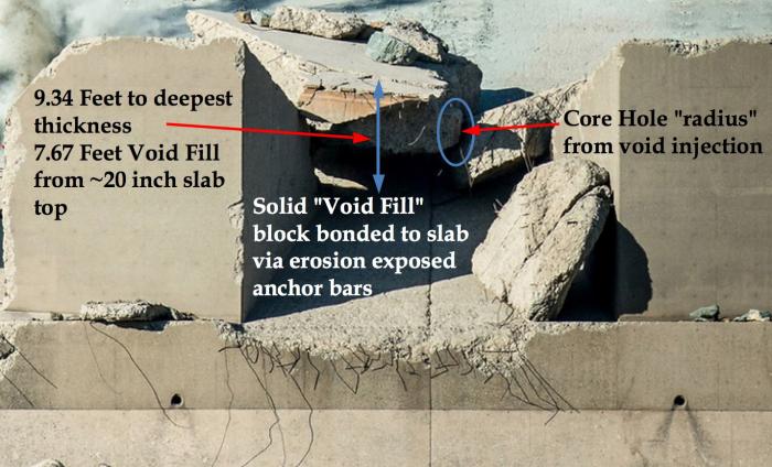
Fig 11. Thickness of Large Block reveals a 9.34 Foot overall thickness and a 7.67 foot thickness of the "void fill". The face of the ends of the large block reveals the notch orientation of an "expansion joint" (per HYD-510 design specifications). The "segment" sections that slightly protrude at the very top of the seam face are likely from concrete patching repairs that bridged the "expansion" joint seams. The Core Hole outline is observable in the corner of the large block.
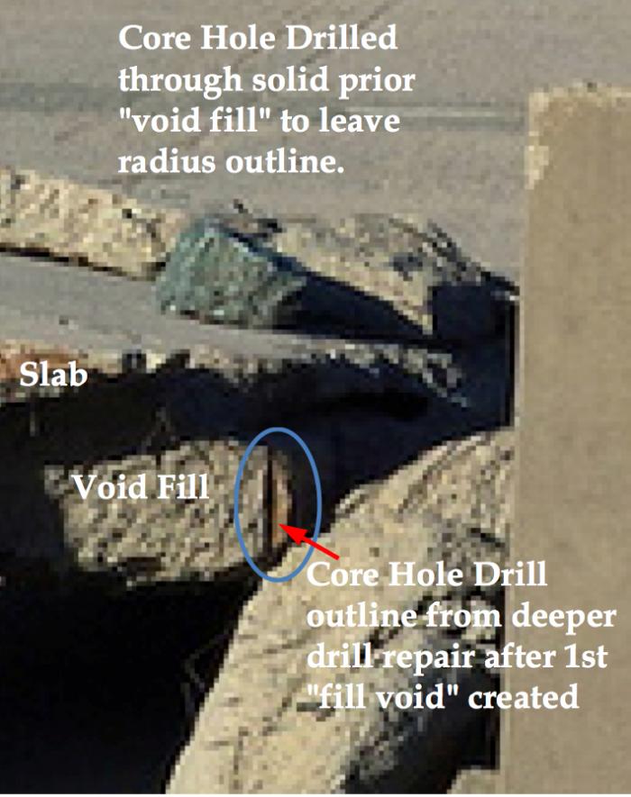
Fig 12. Zoom view of the Core Hole outline in the corner of the large block. Core location to spillway - See Fig 7, Fig 8.
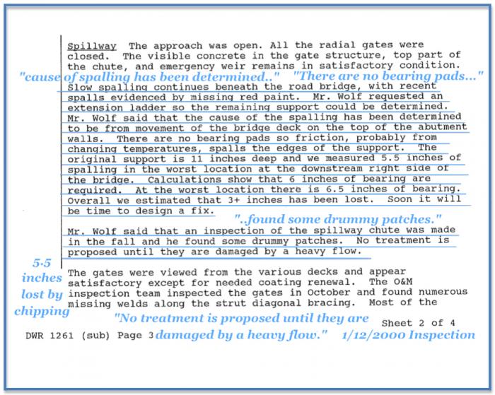
Fig 13. This DSOD 2000 Inspection report reveals a "human" factor that is integral with the management decisions, the engineering decisions, and the repair decisions which provide insight into the contribution of error in engineering judgement. This DSOD inspection report essentially reveals that a collective "engineering outcome" has chosen not to perform repairs on "voids" discovered by acoustic soundings (noted as "drummy patches") until damage occurs from "a heavy flow". This directly implies that the "test" of a potential flaw is in the "outcome" of the existence of "damage" in a known stress condition ("heavy flow"). No discussion of an investigation. This identifies a process of indifference, lack of proper judgement, and a process of "reactive" engineering (i.e. waiting for something to fail, then fix it, rather than pro-actively assessing, inspecting, testing, and improving such that an assured level of performance is KNOWN). The blowout failure exemplifies this "human" factor choice. Many opportunities were presented to identify the early significant failure dangers. Yet, they were not acted upon.
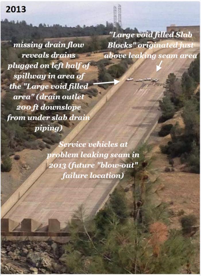
Fig 14. Water seeping up through at the original blowout failure area. Of significance is the lack of drain flow at an outlet. This location identifies that the drains above the seepage area are not functioning. The drains that feed this outlet are in the exact area of the large void fill slab block area.
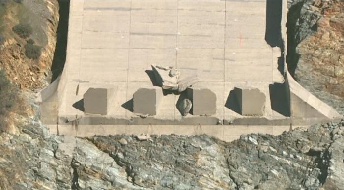
Fig 15. Large Block of concrete at the end of the spillway after the blowout failure. Block originated near (just above) the blowout failure critical seam. Shadow reveals the significance of the thickness of this block.
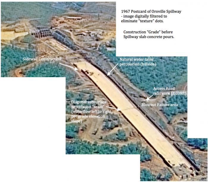
Fig 16. Pre-Spillway slab pour photographs indicate a historic water percolation seam. A water presence would be an indicator to historic weathering of bedrock, leaving seams of highly erodible "weathered rock" sub base. This water percolation seam is located in spillway Blowout failure area. This is area where the Large Chunk of concrete was located near prior to the failure just to left or right center of the spillway. Another example of where DWR engineers should have looked back at photographic evidence to identify that the large void filling areas were likely in a wide seam "channel" of highly erodible weathered rock.
[1] DSOD Jan 12, 2000 Inspection report - sheet 2 (see Fig 13 in this report for pertinent reference).
[2] HYD-510 report, U.S. Department Of The Interior, Sept 30, 1965, Report No. HYD-510 - https://www.usbr.gov/tsc/techreferences/hydraulics_lab/pubs/HYD/HYD-510.pdf
---
'Help Give every Student and Teacher FREE resources for a world-class Moral Catholic Education'
Copyright 2021 - Distributed by Catholic Online
Join the Movement
When you sign up below, you don't just join an email list - you're joining an entire movement for Free world class Catholic education.
An Urgent Message from Sister Sara – Please Watch
- Advent / Christmas
- 7 Morning Prayers
- Mysteries of the Rosary
- Litany of the Bl. Virgin Mary
- Popular Saints
- Popular Prayers
- Female Saints
- Saint Feast Days by Month
- Stations of the Cross
- St. Francis of Assisi
- St. Michael the Archangel
- The Apostles' Creed
- Unfailing Prayer to St. Anthony
- Pray the Rosary
![]()
Copyright 2026 Catholic Online. All materials contained on this site, whether written, audible or visual are the exclusive property of Catholic Online and are protected under U.S. and International copyright laws, © Copyright 2026 Catholic Online. Any unauthorized use, without prior written consent of Catholic Online is strictly forbidden and prohibited.
Catholic Online is a Project of Your Catholic Voice Foundation, a Not-for-Profit Corporation. Your Catholic Voice Foundation has been granted a recognition of tax exemption under Section 501(c)(3) of the Internal Revenue Code. Federal Tax Identification Number: 81-0596847. Your gift is tax-deductible as allowed by law.


