Did Oroville Spillway Break Apart From Design Flaws? Or Poorly understood Stagnation Pressure back in 1960's?
FREE Catholic Classes
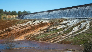
Late January 2017, photographers captured "jackhammering" cavitation erosion at a seam in the spillway prior to it breaking apart. Did this seam reveal the structural stresses within the seriously flawed design of the slabs? New evidence reveals a pre-existing bedrock "seam" of water percolation at the "blowout" failure location of the main spillway. Could this pre-existing bedrock "seam", in combination with the flawed slab design, explain the "missing" waterflow from the spillway drains prior to the "blowout"? Why wasn't DWR aware of the years of "alarms", from "jetting" spillway water drains, as a well known "deadly spillway killer", of Stagnation Pressure Failure?
We ask you, humbly: don't scroll away.
Hi readers, it seems you use Catholic Online a lot; that's great! It's a little awkward to ask, but we need your help. If you have already donated, we sincerely thank you. We're not salespeople, but we depend on donations averaging $14.76 and fewer than 1% of readers give. If you donate just $5.00, the price of your coffee, Catholic Online School could keep thriving. Thank you.Help Now >
Excessive Drain Flow 'Jetting' from Sidewall Outlets signal Alarm in Spillway Slab Cracks & Poor Sealing of Slab seams.
Highlights
Catholic Online (https://www.catholic.org)
4/5/2017 (7 years ago)
Published in Green
Keywords: Oroville, Dam, Spillway, Failure, DWR, Secret, Flaws
LOS ANGELES, CA (California Network) - A "deadly" killer of dam spillways was relatively unknown at the time of Oroville's spillway design and construction in 1967. Only later, when spillways "exploded" in fracturing from uplift pressures at Dickinson Dam, North Dakota, in 1954 and Big Sandy Dam, Wyoming, in 1983, is when dam experts took notice. The "deadly" killer was discovered to be a very powerful uplift force created by aerodynamic principles, called "Stagnation Pressure Failure" [7]. Some refer to this as "hydraulic jacking" in an action similar to a car jack lifting a slab. So alarming was the risk to aging dam spillways, scientists at the Hydraulic Laboratory of the U.S. Department of the Interior, in 2010, studied this effect to alert Dam owners with data in how to predict a spillway failure [3]. From these studies, Oroville's spillway had every single hallmark of design flaws -cracks, open seams, voids, high drain waterflow; to which scientists were trying to warn Dam owners regarding this "deadly" killer. It's now too late to look back. The Oroville Dam spillway has broken in half and is currently in a crisis. Excessive Drain Flow 'Jetting' from Sidewall Outlets signal Alarm in Spillway Slab Cracks & Poor Sealing of Slab seams.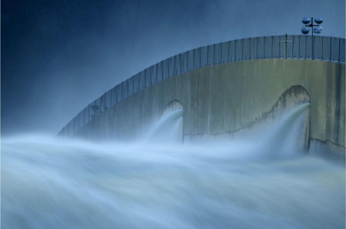
How is the Oroville spillway at risk from Stagnation Pressure Failure & other Flaws? - Here are serious issues that likely were contained in the new BOC findings, but by a FERC filing action by DWR, all reports are now CEII 'Secret' which prevents public access to any documents related to the Oroville spillway incident (P-2100).
Serious Design Flaw Revelations - As based from a newly formed independent panel of experts' report findings, called the Board Of Consultants (BOC), it was revealed that the concrete spillway had such serious flaws so "gross and obvious" that civil design engineers were noting that the BOC reports findings indicated that the spillway could have failed decades earlier [2]. (1) The most serious design flaw was designing drain pipe to be inside the concrete slabs [6]. This flaw resulted in "thinning" zones of the slab thickness, reducing its structural integrity. (2) Aggravating this serious design flaw was a design recommendation from the Oroville Dam Consulting Board to increase the drain pipe from 4-inch inside diameter to 6-inch inside diameter pipe [5]. Because the drain pipe is constructed of thick Vitrified Clay Pipe (VCP), the round shape "bell coupling" joints of this pipe greatly thinned the concrete slab acutely - to where worst-case concrete slab thinning specifications are more serious than what the BOC's first report inferred (commented to be 12 inches and "LESS"). However, actual Design specifications reveal a worst case value could be as thin as 4 to 6 inches. BECAUSE of these 2 issues, there are nearly 5 miles of cracks & patching "fixes" on the entire 3000+ ft length of the spillway! (See Fig 1).
(3) The 360 degree round Bell Coupling VCP pipe "lifted" the drains up from the surface by close to 2 inches. This created an "escape" water flow path beneath the drain pipe that the drains could miss in capturing. Further, (4) Early photographs of the construction of the spillway (See Fig 2), & information revealed from the BOC report, show that a layer of clay & gravel material was placed between the slabs and the bedrock. Thus, it is no surprise that many "voids" have been noted by the BOC report as "escape" waterflow which would erode and "wash" this clay & gravel layer. The BOC report even commented of "channels" of flow or "piping" underneath the slabs - that "this should be investigated". (5) The concrete slabs have contraction joint seams where pressurized water penetrates in flows through these seams at a relatively high rate (i.e. quantity of flow that could be expected for various specific crack and joint geometries). (6) Because of the design decision to emplace the drains inside the slab, this prevented a secondary layer of rebar at the lower area of the slab [6]. note: Modern spillway slab designs have an upper layer of rebar AND a lower layer of rebar to stiffen the slab and protect the complete structural integrity of the thickness of the slab. (7) Oroville's spillway concrete slab seams do not have "water stops" to prevent pressurized water penetration [6]. note: Modern spillway slab designs include these "water stops" to greatly limit the risk of under slab erosive void formation and to limit/prevent Stagnation Pressure [7].
Failure Modes/Flaws - Due to these serious design flaws/issues (noted in 1 thru 7) in the Oroville spillway, the concrete is at an alarming risk or state of a "hydraulic jacking" failure mode (via Stagnation Pressure). Worse, the weakness of the slab in "thinning" zones, are at a high risk from multiple failure mechanisms: (a) Hydraulic Jacking - stressing the slab in an upward structural force, (b) Anchor bars from the bedrock to the slab stressing to "holding secure" under these upward forces (c) Voids forming under the slabs, from excessive under slab waterflow & erosion, causing spillway water load downward structural stress forces (d) Spontaneous "spalling" or chipping of chunks of slab surface layer concrete resulting in a powerful hydraulic "jackhammer" effect from "cavitation erosion" of the slab surface - eventually able to form a "hole". (e) Repeated flexure stressing of the slabs from (a) & (c) causing re-cracking of weak thinning zones, including previous patch repairs. (i.e. many patching repairs at numerous seams in the spillway reveal "chipped" sections that infer the aging concrete is enduring repeated flexure stresses.) (f) Construction Archives revealing that the Gate Section Outlet of the main spillway sits on "lower quality rock than anticipated" (called "weathered rock"/"highly fractured rock"). Because of this poor quality rock, the anchor bars were replaced with "grouted rock bolts, pigtail anchors, and chain-link surface covering" in that area [4].
Cause of First "Blowout" Failure - Image evidence, design flaw evidence, and repeated cracking & repair evidence of (a)(b)(c)(d)(e) is likely the Failure combination leading to the Main Spillway Breaking Apart near the 2039+ ft mark down the spillway. The same evidence is true for the upper spillway (a)(b)(c)(d)(e) with the addition of known areas of poor quality rock (f) in the upper Gate spillway outlet area [4].
Emergency Spillway Again? - The near term operation of the upper spillway will likely continue to be "high risk" even with current efforts to reinforce and attempts to lessen these serious design flaws. During reservoir lowering flows, all it takes is one lurking fracture failure "blowout" within a single weakened slab to break open another crisis-triggering shut-down down in the usability of the main spillway. This could again trigger usage of the Emergency Spillway.
The recent significant repair work in armoring of the Emergency Spillway may reveal an anticipated possibility, of a sudden event in the upper main spillway, by the experts in the know.
(note: a few weeks ago DWR constructed an inspection footpath on the west sidewall for continuous observation by personnel when the upper main spillway is in operation - any fracture or sudden damage may be limited if responded to swiftly by an emergency shut-down. High intensity lighting systems provides night illumination during spillway operation for the continuous observation).
Expert in Stagnation Pressure Failure - It is not surprising that one of the FERC recommended contributing experts to the BOC panel is a renowned specialist in analyzing and predicting Stagnation Pressure Failure in modern dam spillways, Mr. John Trojanowski. He has worked with the Army Corps of Engineers to create a Spillway Tool to assess failure potential of spillways from his extensive knowledge of foundation erosion and hydraulic jacking potential failure modes at joints and cracks in spillways.
Perhaps the public should be asking DWR - Why wasn't DWR aware of the years of "alarms", from "jetting" spillway water drains, as a well known "deadly spillway killer", of Stagnation Pressure Failure? [1]. The cost of repair of these flaws in the dry years would have been far less than the crisis & uncertainty than the exorbitant spillway repair & replacement costs faced today.
Fig 1. Serious Design Flaw of thinning & weakening of the spillway concrete slabs from Drain pipe within the slabs. This has caused over 5 miles of cracks to form as seen in the "herringbone" pattern of drains. Image reveals the cracks and repeated patching as whitish strips. This image is over the area of the spillway that "broke in half". Image courtesy of Google Earth.
Fig 2. 1967 Construction photograph revealing a natural water table percolation flow on a clay & gravel inferred compacted layer. This clay & gravel layer was emplaced before the pouring of the main spillway concrete slabs. Of note is the Diagonal subsurface percolation "seam" revealed at the intersection of the downslope flow of the upper hillside water. This diagonal "seam" is at the location of where the spillway experienced a "blowout" failure. This location is also where spillway drains had "missing" waterflow from the sidewall outlets. Where did the water flow?
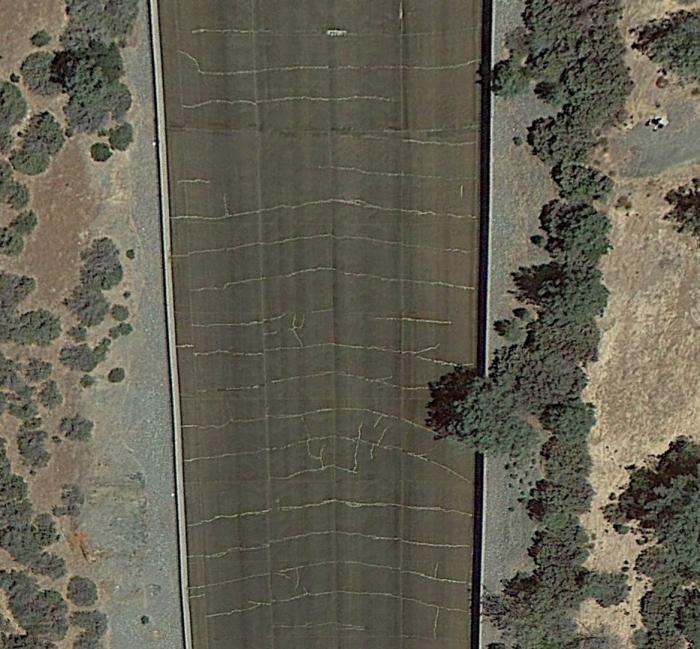
Fig 1. Serious Design Flaw of thinning & weakening of the spillway concrete slabs from Drain pipe within the slabs. This has caused over 5 miles of cracks to form as seen in the "herringbone" pattern of drains. Image reveals the cracks and repeated patching as whitish strips. This image is over the area of the spillway that "broke in half". Image courtesy of Google Earth.
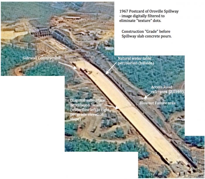
Fig 2. 1967 Construction photograph revealing a natural water table percolation flow on a clay & gravel inferred compacted layer. This clay & gravel layer was emplaced before the pouring of the main spillway concrete slabs. Of note is the Diagonal subsurface percolation "seam" revealed at the intersection of the downslope flow of the upper hillside water. This diagonal "seam" is at the location of where the spillway experienced a "blowout" failure. This location is also where spillway drains had "missing" waterflow from the sidewall outlets. Where did the water flow?
More Reading:
[1] "Alarms Raised Years Ago About Risks of Oroville Dam's Spillways" The San Francisco Chronicle http://www.govtech.com/em/disaster/Alarms-raised-years-ago-about-risks-of-Oroville-Dams-spillways.html
[2] "Damage, design flaws in Oroville Dam spillway point to lengthy repairs, consultants say" The Sacramento Bee http://www.sacbee.com/news/state/california/water-and-drought/article140390898.html
[3] "Predicting Spillway Failure" Hydroworld.com http://www.hydroworld.com/articles/hr/print/volume-29/issue-7/articles/predicting-spillway-failure.html
[4] "The slopes in the flood control outlet gate section proved to be of a lower quality rock than anticipated. There were several large seams running parallel with the chute. The planned anchor bars were replaced with grouted rock bolts, pigtail anchors, and chain- link surface covering in that area." California state water project archives, Oroville Main Spillway https://archive.org/stream/zh9californiastatew2003calirich#page/132/mode/2up/search/lower+quality+rock
[5] "The original 4-inch-diameter, horizontal, pipe drains under the chute were redesigned in accordance with a recommendation from the Oroville Dam Consulting Board. The pipes were placed in a herringbone pattern to give them a downward slope and enlarged to a 6-inch diameter."
California state water project archives, Oroville Spillway Drain System https://archive.org/stream/zh9californiastatew2003calirich#page/132/mode/2up
[6] "Drain Pipe within Slab - Detail A, no waterstop in slab joint, Single Layer of Rebar in Slab top - Typical Detail(s)" Figure 93, Report HYD-510 https://www.usbr.gov/tsc/techreferences/hydraulics_lab/pubs/HYD/HYD-510.pdf
[7] "VI-1. Stagnation Pressure Failure of Spillway Chutes" https://www.usbr.gov/ssle/damsafety/risk/BestPractices/Chapters/VI-1-20150610.pdf
 Hi readers, it seems you use Catholic Online a lot; that's great! It's a little awkward to ask, but we need your help. If you have already donated, we sincerely thank you. We're not salespeople, but we depend on donations averaging $14.76 and fewer than 1% of readers give. If you donate just $5.00, the price of your coffee, Catholic Online School could keep thriving. Thank you. Help Now >
---
'Help Give every Student and Teacher FREE resources for a world-class Moral Catholic Education'
Copyright 2021 - Distributed by Catholic Online
We ask you, humbly: don't scroll away.
Hi readers, it seems you use Catholic Online a lot; that's great! It's a little awkward to ask, but we need your help. If you have already donated, we sincerely thank you. We're not salespeople, but we depend on donations averaging $14.76 and fewer than 1% of readers give. If you donate just $5.00, the price of your coffee, Catholic Online School could keep thriving. Thank you.Help Now >





 Daily Readings for Friday, April 19, 2024
 St. Alphege: Saint of the Day for Friday, April 19, 2024
 Stewardship Prayer: Prayer of the Day for Friday, April 19, 2024

